Imagine having a system in place that could detect fire in its early stages, potentially saving lives and property. This is exactly what you can achieve with an Arduino and a flame sensor. This guide will provide a comprehensive walkthrough of how to use a flame sensor with Arduino, complete with practical applications, step-by-step instructions, and easy-to-follow Arduino code.
What Is a Flame Sensor and Why Should You Use It?
A flame sensor is a device that detects infrared light produced by fire. It is often used in safety systems to monitor for flames or fire. These sensors are affordable and incredibly effective, making them ideal for various projects like:
-
Home fire detection systems
-
Robotics with fire-fighting capabilities
-
Industrial safety systems
With an Arduino board and a flame sensor, you can create projects that detect flames and trigger alerts, such as activating a buzzer, sending notifications, or controlling other devices like sprinklers or fans.
Materials Needed for This Project
Before going into the step-by-step process, gather the following components:
-
Arduino Uno (or any compatible board)
-
Flame sensor module
-
Buzzer (I'm using a piezo buzzer for this project) learn more about piezo buzzer here
-
LED
-
Resistors (220 ohms for the LED)
-
Breadboard and jumper wires
-
USB cable and Arduino IDE installed
A Closer Look at the HW-072 Flame Sensor Module
One of the most popular flame sensors used in Arduino projects is the HW-072 Flame Sensor Module. It's a compact and affordable sensor that's ideal for DIY fire detection systems, educational experiments, and robotics applications. If you've purchased a flame sensor online or as part of a starter kit, there's a good chance it's the HW-072 model.
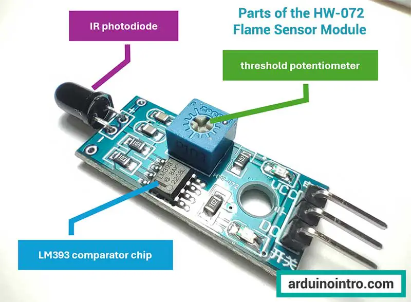
Key Features of the HW-072 Flame Sensor
Here are the main features that make the HW-072 a go-to choice for makers:
-
Uses an IR receiver (typically a photodiode) tuned to detect infrared light in the 760 nm to 1100 nm range, which is the typical wavelength emitted by fire.
-
Built-in LM393 comparator chip that converts analog IR readings into a stable digital signal.
-
Offers both digital (DO) and analog (AO) output pins:
-
DO: Outputs HIGH or LOW depending on flame detection (threshold set by onboard potentiometer).
-
AO: Outputs variable voltage based on IR intensity, allowing detection of flame distance and intensity.
-
-
Has an onboard adjustable potentiometer to fine-tune the detection threshold for the digital output.
-
Status LED indicators: One shows power (usually green), and the other indicates flame detection (usually red).
-
Compatible with 3.3V and 5V Arduino boards, making it flexible for various microcontroller platforms.
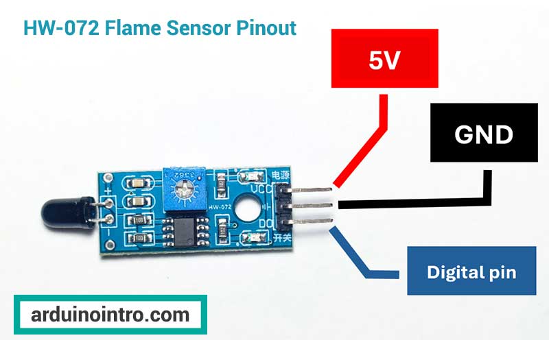
HW-072 Flame Sensor Pinout
Here’s a quick reference for connecting the HW-072 to your Arduino:
| HW-072 Pin | Function |
|---|---|
| VCC | Connect to 3.3V or 5V |
| GND | Connect to GND |
| DO | Digital Output (HIGH/LOW) |
| AO | Analog Output (0–1023) |
Understanding the LM393 Chip in Flame Sensors
Most flame sensors used in Arduino projects are built around the LM393 comparator chip. This integrated circuit plays a crucial role in interpreting the signal from the flame sensor’s photodiode (usually an IR receiver) and providing a stable digital output to your Arduino.
What Does the LM393 Do?
The LM393 is a voltage comparator. It constantly compares the voltage coming from the IR photodiode (which changes when a flame is present) with a preset reference voltage set by a potentiometer on the sensor module.
-
If the detected flame IR level exceeds the reference threshold, the LM393 outputs a LOW signal to the Arduino — indicating a flame is detected.
-
If the signal is below the threshold, it outputs a HIGH signal — meaning no flame detected.
This reliable threshold-based switching mechanism makes the LM393-based flame sensor ideal for DIY fire detection systems using Arduino, especially when using the digital output (DO) pin.
Step-by-Step Guide to Connecting the Flame Sensor to Arduino
-
Understand the Flame Sensor Pins
The flame sensor module typically has three pins:-
VCC: Connects to 5V power supply.
-
GND: Ground connection.
-
DO: Digital output, used to detect the presence of a flame.
-
-
Wiring the Circuit
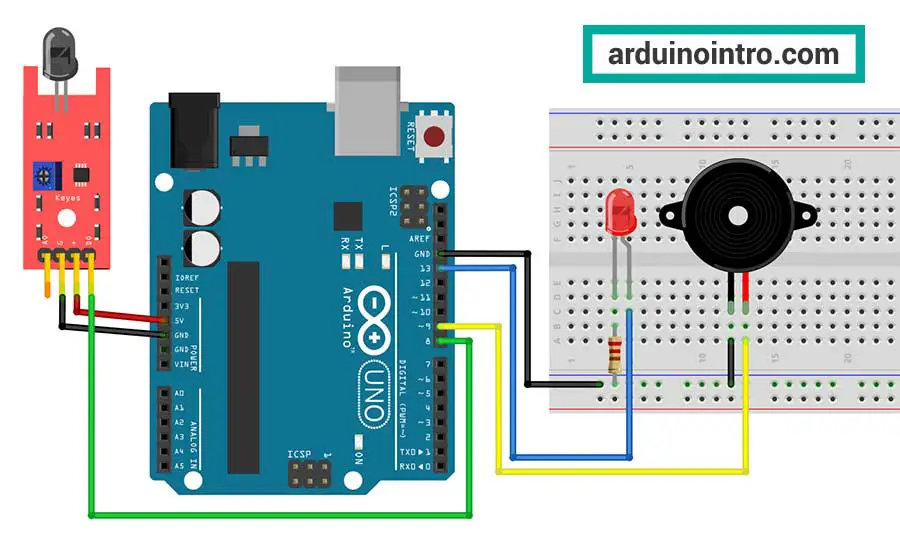
Follow the wiring diagram below:-
Connect the VCC pin of the flame sensor to the 5V pin on the Arduino.
-
Connect the GND pin of the sensor to the GND pin on the Arduino.
-
Connect the DO pin of the sensor to digital pin 8 on the Arduino.
-
Attach the LED to digital pin 13, with a 220-ohm resistor in series.
-
Connect the buzzer to digital pin 9.
-
-
Verify Your Connections
Double-check all the connections before proceeding to coding.
For a better understanding of the piezo buzzer, read this article: Exploring Piezo Buzzer Integration with Arduino: A Comprehensive Guide
Arduino Code for Flame Sensor
Below is a sample code that detects flames and triggers an alert using an LED and a buzzer.
const int flamePin = 8; // Pin connected to flame sensor's DO pin
const int ledPin = 13;  // LED pin
const int buzzerPin = 9; // Buzzer pin

void setup() {
  pinMode(flamePin, INPUT);
  pinMode(ledPin, OUTPUT);
  pinMode(buzzerPin, OUTPUT);
  Serial.begin(9600); // Initialize serial communication
}

void loop() {
  int flameDetected = digitalRead(flamePin); // Read flame sensor output

  if (flameDetected == LOW) { // LOW indicates flame detected
    Serial.println("Flame detected!");
    digitalWrite(ledPin, HIGH); // Turn on LED
    digitalWrite(buzzerPin, HIGH); // Activate buzzer
  } else {
    Serial.println("No flame detected.");
    digitalWrite(ledPin, LOW); // Turn off LED
    digitalWrite(buzzerPin, LOW); // Deactivate buzzer
  }

  delay(100); // Delay for stability
}
Code Explanation
-
Define Pin Connections
At the beginning of the code, constants are defined for the flame sensor, LED, and buzzer pins. -
Setup Function
-
pinMode()sets the pin modes for the sensor, LED, and buzzer. -
Serial.begin(9600)initializes serial communication for debugging.
-
-
Loop Function
-
The flame sensor output is read using
digitalRead(). -
If a flame is detected (
LOW), the LED and buzzer are activated. -
If no flame is detected (
HIGH), both are deactivated.
-
-
Serial Output
-
The serial monitor displays real-time messages, helping you understand the sensor’s readings.
-
Testing and Debugging
-
Open the Serial Monitor
Upload the code and open the Serial Monitor in the Arduino IDE. Verify the sensor's response by exposing it to a flame (e.g., a lighter or candle). -
Calibrate the Sensor
Some flame sensors come with a potentiometer for sensitivity adjustment. Experiment with the settings to get optimal results. -
Safety First
Always handle fire sources with care during testing. Keep a fire extinguisher nearby.
Simulate a Fire Alarm Siren
Let's modify this project by simulating a fire truck-style alarm. Instead of a simple beep, we’ll generate a two-tone siren sound (alternating between two distinct tones repeating in a steady rhythm) that mimics a real emergency alarm, making it more attention-grabbing.
Here's the modified code using the tone() function to simulate a fire alarm siren, similar to a fire truck:
const int flamePin = 8; // Pin connected to flame sensor's DO pin
const int ledPin = 13;  // LED pin
const int buzzerPin = 9; // Buzzer pin

void setup() {
  pinMode(flamePin, INPUT);
  pinMode(ledPin, OUTPUT);
  Serial.begin(9600); // Initialize serial communication
}

void loop() {
  int flameDetected = digitalRead(flamePin); // Read flame sensor output

  if (flameDetected == LOW) { // LOW indicates flame detected
    Serial.println("Flame detected!");
    digitalWrite(ledPin, HIGH); // Turn on LED
    fireAlarm(); // Simulate fire alarm siren
  } else {
    Serial.println("No flame detected.");
    digitalWrite(ledPin, LOW); // Turn off LED
    noTone(buzzerPin); // Stop buzzer sound
  }

  delay(100); // Delay for stability
}

// Function to simulate fire alarm siren
void fireAlarm() {
  int highTone = 1000; // High pitch frequency (Hz)
  int lowTone = 600;   // Low pitch frequency (Hz)
  int duration = 400;  // Duration of each tone (milliseconds)

  // Play alternating high and low tones
  for (int i = 0; i < 5; i++) { // Repeat the siren pattern 5 times
    tone(buzzerPin, highTone);
    delay(duration);
    tone(buzzerPin, lowTone);
    delay(duration);
  }

  noTone(buzzerPin); // Stop the buzzer after the loop
}
Explanation of Changes
-
Added
fireAlarm()Function-
This function generates a siren effect by continuously increasing and then decreasing the frequency of the sound.
-
The
tone()function is used to produce sound at the specified frequency.
-
-
Inside the
loop()Function-
When a flame is detected (
LOW), thefireAlarm()function is called, and the LED is turned on. -
If no flame is detected (
HIGH), thenoTone()function stops the buzzer sound.
-
-
Customizable Siren Effect
-
The siren frequency range (500 Hz to 1000 Hz) and delay (10 ms) can be adjusted to modify the siren’s speed and pitch.
-
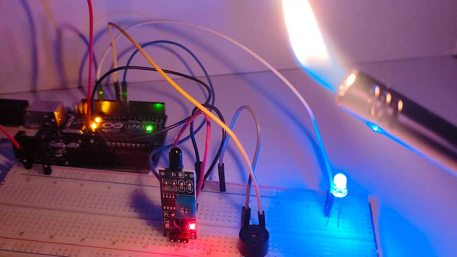
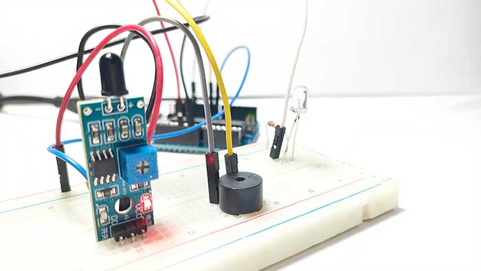
Here's my simple flame sensor alarm project:
Using the Flame Sensor's Analog Pin
Here’s another version of the code that uses the analog pin to read the flame sensor's output. Using an analog pin allows us to measure the intensity of the detected flame by reading varying voltage levels.
Updated Arduino Code (Using an Analog Pin)
const int flamePin = A0; // Analog pin connected to flame sensor's AO pin
const int ledPin = 13;   // LED pin
const int buzzerPin = 9; // Buzzer pin

// Flame detection threshold (adjust based on your sensor and environment)
const int threshold = 300;

void setup() {
  pinMode(ledPin, OUTPUT);
  pinMode(buzzerPin, OUTPUT);
  Serial.begin(9600); // Initialize serial communication
}

void loop() {
  int flameIntensity = analogRead(flamePin); // Read analog value from flame sensor
  Serial.print("Flame Sensor Value: ");
  Serial.println(flameIntensity);

  if (flameIntensity < threshold) { // Flame detected
    Serial.println("Flame detected!");
    digitalWrite(ledPin, HIGH); // Turn on LED
    fireAlarm(); // Simulate fire alarm siren
  } else {
    Serial.println("No flame detected.");
    digitalWrite(ledPin, LOW); // Turn off LED
    noTone(buzzerPin); // Stop buzzer sound
  }

  delay(100); // Delay for stability
}

// Function to simulate fire alarm siren
void fireAlarm() {
  for (int freq = 500; freq <= 1000; freq += 10) { // Ascending frequency
    tone(buzzerPin, freq);
    delay(10);
  }
  for (int freq = 1000; freq >= 500; freq -= 10) { // Descending frequency
    tone(buzzerPin, freq);
    delay(10);
  }
}
Explanation of Changes
-
Using
analogRead()-
The flame sensor’s AO pin (Analog Output) is connected to the Arduino's A0 pin.
-
The
analogRead()function reads a value between 0 and 1023, representing the intensity of the flame.
-
-
Threshold for Flame Detection
-
A threshold value (300 in this example) is defined to determine whether a flame is present.
-
If the analog reading is below the threshold, a flame is detected. Adjust this value based on your environment and sensor sensitivity.
-
-
Flame Intensity Monitoring
-
The flame sensor value is printed to the Serial Monitor, allowing you to observe real-time data and adjust the threshold if needed.
-
-
Alarm and LED Behavior
-
When a flame is detected, the LED turns on, and the buzzer emits a fire truck-like siren using the
fireAlarm()function. -
When no flame is detected, the LED turns off, and the buzzer stops with
noTone().
-
Advantages of Using an Analog Pin
-
Increased Sensitivity: Allows you to measure flame intensity, not just detect its presence.
-
Customizable Threshold: Offers flexibility for different environments and sensor variations.
This version of the code provides enhanced functionality by leveraging the analog output of the flame sensor, making it ideal for projects requiring more precise flame detection.
Watch how I built a DIY fire alarm system using the HW-072 flame sensor, Arduino, LED, and a two-tone fire truck siren.
Flame Sensor Detection Range and Direction
When designing your project, it’s important to understand the physical limits of the flame sensor in terms of distance and angle.
Detection Distance
-
Most common flame sensors can detect a flame from approximately 30 cm to 80 cm (about 12 to 32 inches) under normal indoor lighting conditions.
-
The range depends on:
-
The size of the flame (larger flames emit more infrared light).
-
Ambient lighting (bright sunlight or reflective surfaces may interfere).
-
Sensor quality and IR filter sensitivity.
-
Detection Direction (Viewing Angle)
-
Most flame sensors have a detection angle of about 60 to 120 degrees.
-
This means it works best when the flame is directly in front of the sensor.
-
If you're using the sensor in a wider room or need 360° coverage, consider mounting multiple sensors in different directions for better flame tracking.
How the LM393 and Detection Specs Help You Build Smarter Projects
Understanding how the LM393 chip processes IR signals, and knowing the effective detection range and direction, allows you to design more reliable fire detection systems. For example:
-
You can position the flame sensor within the correct range to cover a gas stove or candle.
-
You can program your Arduino to react only when flames are close enough to be a threat.
-
You can calibrate the sensitivity so that your project doesn’t trigger false alarms due to heat from a lightbulb or sunlight.
Performance Tips for HW-072 Users
Here are a few tips to help you get the most out of your HW-072 flame sensor module:
-
Keep the sensor clean: Dust and smoke residue can reduce accuracy.
-
Avoid direct sunlight: Bright IR sources like the sun can trigger false alarms.
-
Use shielding or enclosures: If the sensor is placed in windy or bright environments, use a shroud or shield to improve performance.
-
Fine-tune the potentiometer: Use the onboard screw to adjust sensitivity — clockwise usually increases sensitivity, counter-clockwise decreases it.
Conclusion
The HW-072 flame sensor module is a powerful yet beginner-friendly sensor that makes it easy to detect flames using an Arduino. Thanks to its built-in LM393 comparator, dual analog and digital outputs, and adjustable sensitivity, it offers both simplicity and flexibility for any fire detection or safety automation project.
By following this guide, you’ve learned how to use a flame sensor with Arduino, wire the components, upload the code, and test the system effectively. This project is a great starting point for anyone new to Arduino and provides valuable skills for creating safety-focused applications.


