Ever wanted to control a light with your phone like a boss? In this fun and beginner-friendly tutorial, I’ll walk you through how to control an LED with an Arduino using the HC-05 Bluetooth module and a free Android app called Connectino. No Wi-Fi? No problem. This project is a great way to dip your toes into wireless control and Arduino programming.
Imagine building your own DIY smart lamp that you can turn on or off from across the room—or even outside your house. This same concept can be extended to control fans, appliances, and even robots.
What Will You Learn in This Guide?
- What the HC-05 Bluetooth module is and how it works
- How to wire it safely to an Arduino using a voltage divider
- How to control LEDs using the Connectino Android app
- Detailed explanation of the Arduino code
- A real-world application idea to inspire your project
What Can I Use This For?
Controlling one LED might seem simple, but this is the foundation of countless DIY and smart home projects. You can use this setup to:
- Build a wireless desk lamp
- Create a simple notification system
- Add remote control to decorations or displays
- Learn how to scale up to controlling motors, relays, or more lights later on!
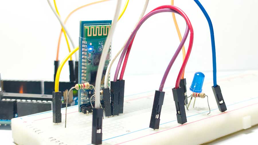
Controlling an LED in Arduino using Bluetooth and Connectino app is very easy. Here's a demo of my simple HC-05 setup.
What You'll Need
|
Component |
Quantity |
|
Arduino Uno (or Nano) |
1 |
|
HC-05 Bluetooth module |
1 |
|
LED |
1 |
|
220-ohm resistor |
1 |
|
Breadboard |
1 |
|
Jumper wires |
Several |
|
Android smartphone |
1 |
|
Connectino app (free) |
1 |
|
5K-ohm resistor |
1 |
|
10K-ohm resistor |
1 |
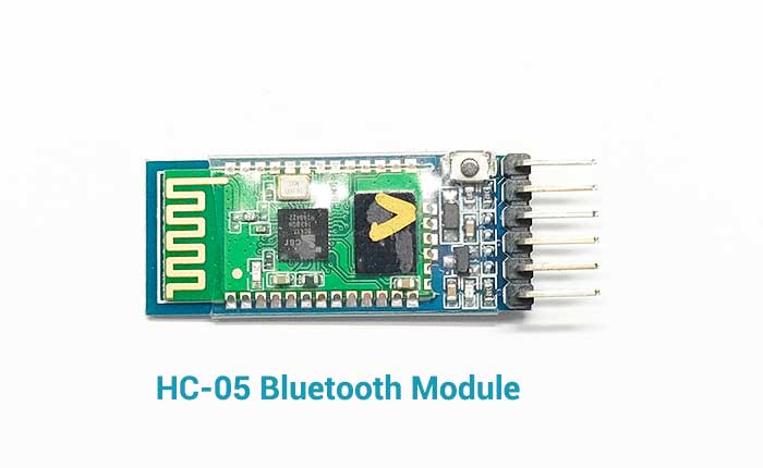
What is the HC-05 Bluetooth Module?
The HC-05 Bluetooth module is a low-cost, easy-to-use module that allows your Arduino to communicate wirelessly with other Bluetooth-enabled devices, like Android phones, tablets, or even laptops.
It supports Bluetooth 2.0 with a range of about 10 meters (33 feet), making it ideal for short-range wireless control projects like controlling LEDs, robots, relays, or sensors from your smartphone.
It operates on 3.3V logic, which is why we’ll use a simple voltage divider with a 5K and 10K resistor to protect it.
Why You Need a Voltage Divider When Connecting Arduino to HC-05
A voltage divider is a simple and safe way to reduce the 5V signal from the Arduino to around 3.3V before it reaches the HC-05.
The HC-05 Bluetooth module communicates using 3.3V logic, meaning it expects the data it receives (on its RX pin) to be no higher than 3.3 volts. However, the Arduino Uno uses 5V logic, so it sends out 5V signals from its TX (transmit) pin.
Sending 5V signals directly to the HC-05's RX pin can damage the module over time, since it's not designed to handle more than 3.3V on that pin.
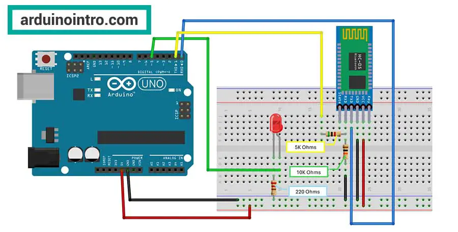
Voltage Divider Circuit
You can create a voltage divider using two resistors — for example:
- 5kΩ (R1)
- 10kΩ (R2)
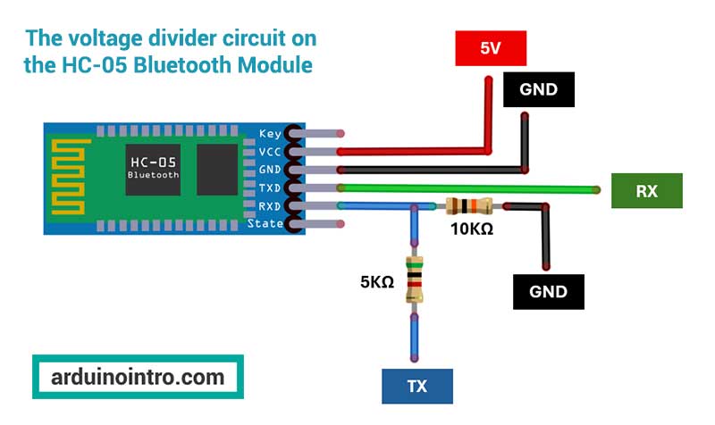
To protect the HC-05, we use a voltage divider on the Arduino TX → HC-05 RX line. Here’s how it works:
- Connect Arduino TX to one end of the 5kΩ resistor (R1).
- Connect the other end of R1 to one end of the 10kΩ resistor (R2).
- Also from that same junction (between R1 and R2), connect a wire to the HC-05 RX pin.
- Connect the other end of R2 to GND.
This converts the 5V signal to a safe ~3.3V, protecting the module.
Yes, you can use other resistor values as long as the ratio is 1:2 — for example, 1kΩ and 2kΩ would work the same way. The voltage output depends on the ratio between the two resistors, not their absolute values.
Advantages of Using Higher Resistor Values (like 5kΩ and 10kΩ):
- Less current draw, which is better for power efficiency.
- Still works perfectly for low-speed serial communication (like Bluetooth).
Just make sure:
- The resistor ratio is 1:2 (e.g., 1kΩ and 2kΩ, or 5kΩ and 10kΩ).
- You place them correctly:
- R1 goes between Arduino TX and the HC-05 RX line.
- R2 goes from the junction to GND.
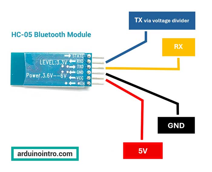
HC-05 Pinout Explained:
|
Pin |
Function |
|
EN |
Enable pin (optional, for AT mode) |
|
VCC |
Power supply (connect to 5V on Arduino) |
|
GND |
Ground |
|
TXD |
Transmit data (connects to Arduino RX) |
|
RXD |
Receive data (connects to Arduino TX via voltage divider!) |
|
STATE |
Output pin to indicate connection status (optional) |
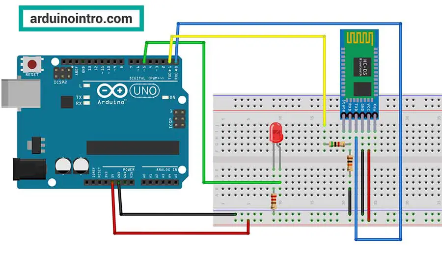
Wiring Diagram Summary
- LED → Pin 5
- HC-05 VCC → 5V on Arduino
- HC-05 GND → GND on Arduino
- HC-05 TX → Arduino RX (pin 0)
- HC-05 RX → Arduino TX (pin 1) via voltage divider
Important: Disconnect the HC-05 TX and RX wires before uploading code, then reconnect them afterward.
The Arduino Code
Here's the code that powers everything:
/*Connectino: Arduino Bluetooth Control
 * by Ramski Studios
Sample code for Switches

Make sure to disconnect the TX and RX (0 and 1) jumper wires
from the Arduino board before uploading the sketch.
You may attach the wires again after it is done uploading.
*/

int led1 = 5; // LED connected to pin 5

void setup() {
    Serial.begin(9600);          // Start serial communication
    pinMode(led1, OUTPUT);       // Set pin 5 as output
}

void loop() {
    if (Serial.available() > 0) {               // Check for data from Bluetooth
        String command = Serial.readString();   // Read the incoming message

        if (command.equals("SWITCH1_ON")) {
            Serial.print("LED 1 is ON");
            digitalWrite(led1, HIGH);           // Turn LED on
        }
        else if (command.equals("SWITCH1_OFF")) {
            Serial.print("LED 1 is OFF");
            digitalWrite(led1, LOW);            // Turn LED off
        }
    }
}
How the Code Works
- Serial.begin(9600); starts the communication with the HC-05.
- pinMode(led1, OUTPUT); tells the Arduino that pin 5 will control an LED.
- The loop() constantly checks if any data comes in via Bluetooth.
- When you press a toggle switch in the Connectino app, it sends either "SWITCH1_ON" or "SWITCH1_OFF".
- If "SWITCH1_ON" is received, the LED turns on.
- If "SWITCH1_OFF" is received, the LED turns off.
- Serial.print() sends a response back to the app so you can see what the Arduino did.
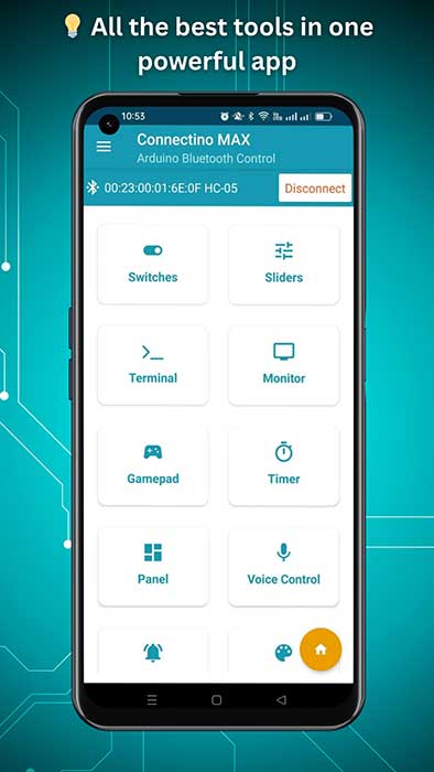
Set Up the Connectino App
To control your Arduino with your smartphone, we’ll use a free Android app called Connectino Arduino Bluetooth Control by Ramski Studios. It’s designed specifically for beginners and hobbyists working with Arduino and Bluetooth.
How to Set It Up
- Install the App
Open the Google Play Store, search for “Connectino Arduino Bluetooth Control by Ramski Studios”, and install it. It’s completely free.
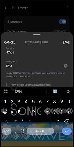
- Pair the HC-05 Bluetooth Module
Before you open the app, go to your phone’s Bluetooth settings and pair your phone with the HC-05. The default pairing PIN is usually 1234 or 0000.
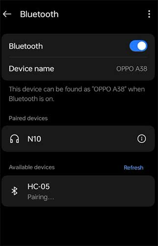
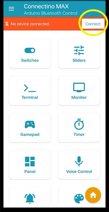
- Connect in the App
-
- Launch the Connectino
- Tap "Connect" in the menu.
- Select your paired HC-05 device from the list.
- Once connected, you’ll be able to use the toggle switches function of the app.
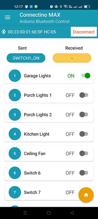
- Control Your LED
Flip the Switch 1 toggle to ON or OFF and watch the LED respond instantly via Bluetooth!
Testing Your Project
- Upload the code to your Arduino (remember to remove TX/RX wires first).
- Reconnect the TX and RX wires.
- Power your Arduino.
- Open Connectino and connect to your HC-05.
- Toggle the switches — your LEDs should respond immediately!
Watch this step-by-step video tutorial to learn how to control an LED using your smartphone, Arduino Uno, and the HC-05 Bluetooth module.
Frequently Asked Questions (FAQs)
- Do I need an internet connection for this project?
No, this project works entirely over Bluetooth and does not require Wi-Fi or internet access.
- What phones are compatible with Connectino?
Any Android phone with Bluetooth and running Android 5.0 or higher should work fine.
- Can I add more features later?
Yes! You can expand this project to control multiple LEDs, motors, or even sensors.
- Why is my HC-05 not showing up?
Make sure your Arduino is powered, and check the wiring. Also, ensure the Bluetooth module is blinking red (indicating it's discoverable).
Final Thoughts
Controlling multiple LEDs with Arduino using the HC-05 Bluetooth module and the Connectino app is not only easy — it's educational and fun! With just a few components and some simple code, you’ve created a wireless system that mimics how smart devices work.
This tutorial is a great starting point for beginners who want to explore Arduino and Bluetooth communication. With a bit of creativity, you can expand this project into a full smart home prototype!


